Preface
This post is going to cover one of many processes to lift firmware from an Integrated Circuit (IC) chip. There are many methods that can be used such as interfacing with General Purpose Input/Output (GPIO) interfaces (e.g., UART, JTAG, etc.). However, when confronted with the opportunity to extract firmware directly from an IC, the process can be rather uncomplicated as we will demonstrate. Don't worry, we will be demonstrating other techniques necessary to extract firmware in upcoming posts.
Test Environment
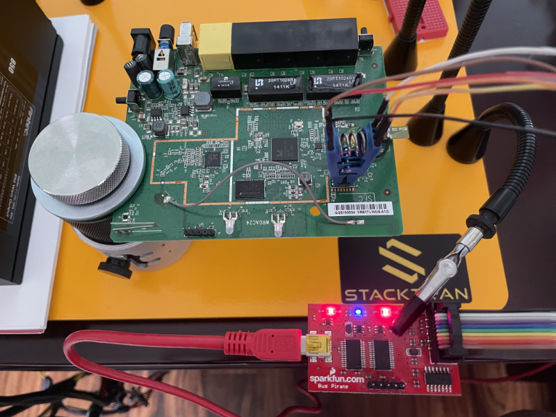
Our sacrificial board is from a D-Link (i.e., D-Link DIR-817LW) donor device, which can be considered a residential class 802.11x wireless router.
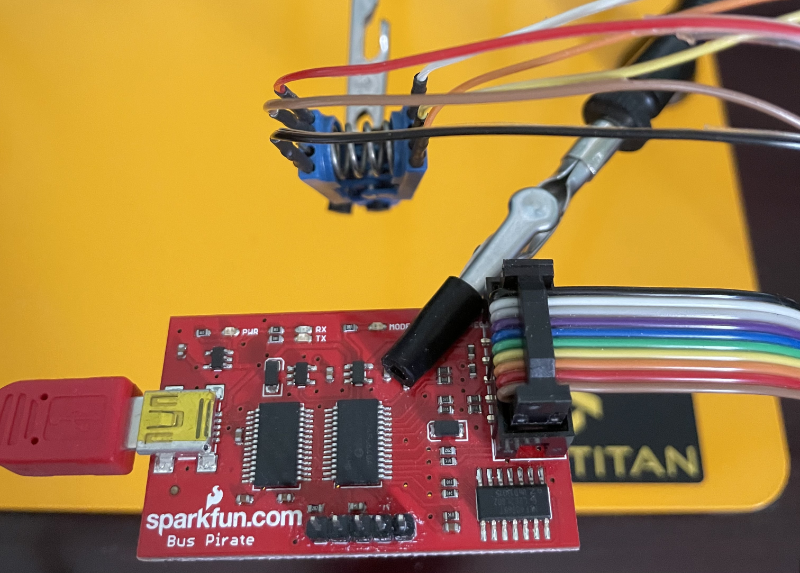
We will use a Pomona Electronics 5250 SOIC test clip to provide direct access to the IC chip. Quality test clips, such as the Pomona brand, can be rather expensive compared to cheaper alternatives, but their dependability justifies the cost when others fail to align to tight IC tolerances.
Lastly, we will use the infamous Bus Pirate as the FTDI interface necessary to communicate with the IC chip's protocol, which is typically either I2C or SPI.
The following photo depicts our lab setup, but we can't make any of the connections until confirming IC chip manufacturer, protocol, pinouts, etc. So let's discuss next...
Inspecting the IC Chip
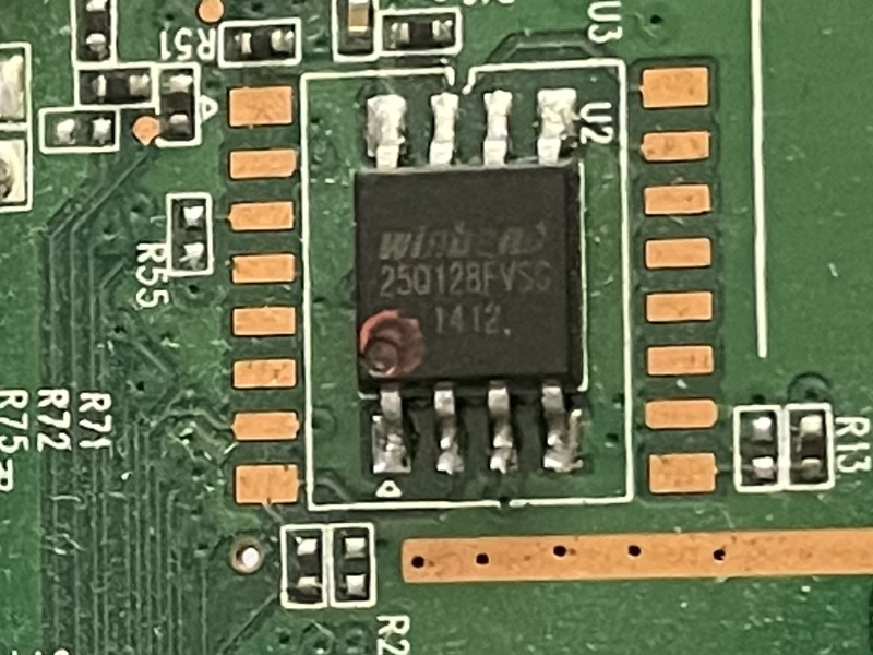
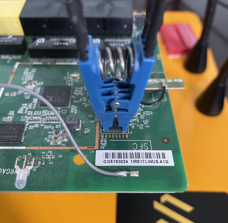
Circuit boards are usually architected with their components situated around quadrants. For example, ethernet components and chips may reside or may rather be compartmentalized in one section of the board, wireless radios and their components in another, and so on. This board follows that same design pattern, whereas the center of the board has what appears to be a multiprocessor package, a Dimm package and an IC. The IC is of interest as it supports non-volatile memory storage, which is perfect for a firmware location.
Inspecting the IC chip, we can see that it is a WinBond W25Q128FV. The reason for obtaining this information should be obvious, but if not, this will allow for further technical referencing via the manufacturer's data-sheet.
Considering the WinBond chip is commodity hardware used in many boards, Digi-key or similar has publicly available data-sheets, which can be located here. Reading the first few pages of the data-sheet provides information that our IC chip is of type Serial Peripheral Interface (SPI) with an operating tolerance between 2.7V and 3.6V. This is enough information to move to the next phase, which consists of wiring the test equipment.
Wiring the Components
Again, referencing the WinBond data-sheet, we can find the pinout for the IC SPI chip. The naming conventions within the data-sheet and the pinout provided on the Bus Pirate are somewhat different, so we have created the following table to make the mapping easier.
| Data-Sheet Pin | Bus-Pirate Pin | Purpose |
|---|---|---|
| CS | CS | Chip Select |
| DO | MISO | Master In Slave Out |
| GND | GND | Ground |
| VCC | +3V3 | Supply Voltage |
| CLK | CLOCK | Signal Clock |
| DI | MOSI | Master Out Slave In |
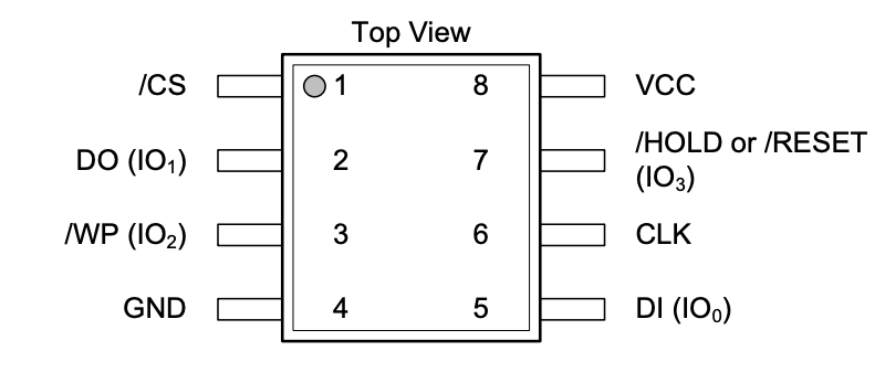
Note the circle on the upper left will indicate the top of the chip. This will also coincide with the indented or raised circle found on the actual physical chip, as to provide a common reference point when wiring for the pinout.
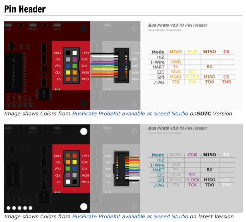
A word of caution when wiring the Bus Pirate. Although DangerousPrototypes created the original Bus Pirate, various versions have been released since then. For example, Seeed Studio and Sparkfun each have their own version, and each have different colored wiring schemes, so take note of your version and wire accordingly.
Once wired, the Pomona SOIC test clip should look similar to that depicted within the image below. Again from a top-down view of the test clip, the upper-left should have CS and the lower-right should end with MOSI.
Finishing Up
This section is provided to dispel one common question that I believe confuses most when getting into hardware, and that is to power on the board or not to power on the board.
Keep in mind that we are dealing with, and directly accessing, a single IC chip, which we can supply VCC (our own voltage supply). Further, the Bus Pirate can supply 3v3 power, which is well within the operating tolerances of the IC chip. Therefore, there is no need for us to power on the entire board when we can simply supply our own to the single component of interest. Further, providing power to only the IC chip, and not the board as a whole, prevents possible conflicts when reading from the chip as it will refrain from communicating I/O with surrounding peripherals/packages. Providing isolated power to the IC chip is the preferred method here.
However, a reason for powering the entire board may be when dealing with voltages outside of our Bus Pirate's tolerances, or using another method of lifting firmware, such as tying an MPU RESET pin to GROUND in order to introduce an I/O idle or hold state. Again, we will cover this in another post, but this is hacking so it is always good to have options.
With that, make the connection by securing the Pomona SOIC test clip so that the CS pin matches that of the IC chip (recall the circle indent). It should look similar to the following.
Lifting the Firmware
If you stuck with us this far, we have finally arrived! It is time to extract the firmware from this IC chip. To get started we need to make sure that we have a system running the flashrom program. Flashrom supports a myriad of test devices, protocols and chip manufacturers, thus reducing the heavy lifting associated with flash memory manipulation.
In the following we are telling flashrom to use the Bus Pirate and SPI protocol (i.e., buspirate_spi) and passing it the device location (e.g., /dev/ttyUSB0). The dmesg command can be helpful in locating the device when operating from a Linux system. If successful, the WinBond chip should have been found.
stack_lab$ sudo flashrom -p buspirate_spi:dev=/dev/ttyUSB0
flashrom v1.2 on Linux 5.4.0-136-generic (x86_64)
flashrom is free software, get the source code at https://flashrom.org

Using clock_gettime for delay loops (clk_id: 1, resolution: 1ns).
Bus Pirate firmware 6.1 and older does not support SPI speeds above 2 MHz. Limiting speed to 2 MHz.
It is recommended to upgrade to firmware 6.2 or newer.
Found Winbond flash chip "W25Q128.V" (16384 kB, SPI) on buspirate_spi.
No operations were specified.
The next step is similar to prior, however, this time we want to define the speed in which the memory I/O reads are performed. The speed ranges from 30k to 8M, and there is a tradeoff. The lower the read rate, the more accurate the results but at a cost of an extremely lengthy duration. Contrarily, the faster the read the less accurate the results. Providing a speed of 1M is typically a good compromise for both speed and accuracy, albeit still time to make a pot of coffee...slam it..and make another! The -c option simply declares the type of chip and the -r is the name of the file to be created that will contain the firmware.
stack_lab$ sudo flashrom -p buspirate_spi:dev=/dev/ttyUSB0,spispeed=1M -c W25Q128.V -r W25Q128.V.bin
flashrom v1.2 on Linux 5.4.0-136-generic (x86_64)
flashrom is free software, get the source code at https://flashrom.org

Using clock_gettime for delay loops (clk_id: 1, resolution: 1ns).
Found Winbond flash chip "W25Q128.V" (16384 kB, SPI) on buspirate_spi.
Reading flash... done.
Running this after some time should have produced our firmware file, so we might assume success. Trust but verify.
stack_lab$ ls -alh W25Q128.V.bin
-rw-r--r-- 1 root root 16M Jan 28 15:08 W25Q128.V.bin
Just to confirm, we can use the glorious binwalk utility to help parse the firmware file for known data types. The -M options simply tells binwalk to recurse during analysis. As we can see, the file is in fact a firmware that also contains a squashfs file-system. With that, you are left to your own devices to hack on!
stack_lab$ binwalk -M ext_firmware.bin

Scan Time:     2023-02-12 14:03:26
Target File:   W25Q128.V.bin
MD5 Checksum:  b35279b4d39d377f47187ac847f43567
Signatures:    411

DECIMAL       HEXADECIMAL     DESCRIPTION
--------------------------------------------------------------------------------
7104          0x1BC0          LZMA compressed data, properties: 0x5D, dictionary size: 8388608 bytes, uncompressed size: 75376 bytes
196660        0x30034         bzip2 compressed data, block size = 900k
524288        0x80000         TRX firmware header, little endian, image size: 5722112 bytes, CRC32: 0x365EA7FA, flags: 0x0, version: 1, header size: 28 bytes, loader offset: 0x1C, linux kernel offset: 0x1A2D80, rootfs offset: 0x0
524316        0x8001C         LZMA compressed data, properties: 0x5D, dictionary size: 65536 bytes, uncompressed size: 4225056 bytes
917504        0xE0000         SEAMA firmware header, big endian, meta size: 36, image size: 7622688
917536        0xE0020         Unix path: /dev/mtdblock/6
917568        0xE0040         LZMA compressed data, properties: 0x5D, dictionary size: 33554432 bytes, uncompressed size: 4970636 bytes
2490432       0x260040        PackImg section delimiter tag, little endian size: 5266432 bytes; big endian size: 6049792 bytes
2490464       0x260060        Squashfs filesystem, little endian, version 4.0, compression:lzma, size: 6049169 bytes, 2246 inodes, blocksize: 131072 bytes, created: 2014-03-06 09:37:02
Conclusion
We have demonstrated the tools required to lift firmware using a Pomona SOIC test clip, the Bus Pirate, and a few open-source tools. This was in contrast to accessing firmware using common techniques, such as interfacing with UART or JTAG. It is important to understand many methods and techniques when performing hardware hacking, as these technologies and board configurations can always be a challenge. We hope that this post may assist aspiring hardware hackers out there, and provide a common reference for others. Stay tuned, the STACKTITAN team will be posting on more hardware topics very soon.