Why Another Hardware Implant?
Many hardware implants have already been created by hobbyists and commercial companies, alike. We are no different in that regard. However, we use our hardware implants in real-world Red Team operations while constantly evolving the form factor to align with the most effective solution for the mission. These are battle-tested and proven to work. Lessons are learned and changes are applied, as necessary. We thought it might be interesting to some that may be looking to up their field-kit, might not get an opportunity to perform uninhibited breaches of organizations, or simply enjoy learning by practical application.
What we aim to achieve in the next couple of blog posts is to help describe our solution, detail the bill-of-materials, exemplify the build process, and finally live-fire our covert hardware implant (CHI).
The Guiding Criteria for the Build
Ok let's get this out of the way. If you are building and placing a covert implant in an environment that looks like a computer development board (i.e., raspberry pi, Panda, etc.) then expect it to be observed as suspect. Things that look suspect get detected, and things that look less suspicious often times get overlooked. Which leads to the first criteria:
The physical form-factor must be unassuming and must blend into the surrounding environment.
The implant is going to be placed in a hostile environment where detection instrumentation is going to possibly and most likely inspect traffic. This means that relying on command and control (C2) over a traditional corporate enterprise network isn't the best solution. The second criteria:
Command and control communications that supports tool delivery and data exfiltration through out-of-band channels.
In a similar vein, the operational traffic, that which will explore and compromise enterprise systems will be seperate from the C2 communication channel (i.e., traverse a separate network interface on the implant). This comes with a number of other considerations. The most notable would be assuring that enterprise tooling that often proactively scan assets (e.g., vulnerability detection, asset inventory, excessive privilege, etc.) are rendered blind to our device.
The enterprise logical footprint should be as minimal/non-existent as possible.
Finally, the implant should be relatively free of complexity and should be serviceable with minimal effort.
The implant should be able to support easily acquirable commodity hardware so that operators can perform field expedient repairs, as necessary.
Hardware Bill of Materials (BOM)
1. APC Surge Protector (P11VNT3)
A surge protector is an obvious choice that would work in most any corporate environment. Whether it is actually in use or not, nobody is going to question the presence of this form factor. We also set out to find one that supported wired Ethernet ports, as this is going to provide LAN side enterprise connectivity.
After a bit of searching through the endless Amazons, we came upon the APC P11VNT3 model, which seemed to have all the preliminary bones necessary to support our build. The price point was also well within reason at around $40 USD.
2. Raspberry Pi 4 Model B
Either the Pi 3 or Pi 4 should work just fine. The supply and demand seems to have calmed down a bit, and can be located relatively close to MSRP (Buy at Sparkfun) . We are looking to reengineer the solution to use more readily available prototyping boards, but for now this is the proven adaptation.
3. Cellular LTE Components
SIXFAB Pi 4 LTE Hat - This will act as the bridge between the Raspberry Pi and the Telit LTE modem.
SIXFAB LTE Antenna - This is the u.FL connected antenna that supports both LTE and GNSS.
Telit LE910C4 Mini PCIe LTE CAT4 Module - The module serves as the actual LTE modem that will be attached to the SIXFAB LTE Base Hat.
Twilio SIM Card Service - Twilio has partnered with T-Mobile (US) to provide a general pay-as-you-go SIM service for IOT solutions.
4. Miscellaneous Connectors, Cables and Storage
MicroSD Card - Recommend using an SD card with a descent amount of storage and IO speeds. We chose to use both Lexar and Sandisk Ultra 128GB cards, which have met our field requirements.
USB Cable (1 FT USB-C to USB-C) - The inside of the surge protector is rather limited in space, so choose a 6 inch to 1 foot USB-C cable. One end should be a straight connector and the other should be a 90 degree connector.
Leviton Power Cord Plug - The surge protector's power cord will be terminated to this device. We chose to use the original APC power cord due to the cord fitting that secures the cord with the APC case.
Anker USB-C Block Charger - A block charger will provide power to the Raspberry Pi and it's inherent LTE components.
Adhesive Backed 1/16" Silicon Rubber Sheet - The silicone sheeting will be cut to adhere to the internal bottom side of the APC case. It is a tight fight, so the combination of the rubber anti-slip surface and snug fit of the closed case will prevent the internals from sliding around.
Brass Spacer Standoff Kit - This is just a general purpose kit to make it easier to fit the LTE hat onto the Raspberry Pi 4.
Dismantling and Clearancing
The first thing we want to do is dismantle the housing in order to see what we're dealing with, so that we can start to piece together our new internal components. Note that this particular APC uses security screws, so you will want to use a "spanner" screwdriver to decouple the back from the front pans.
At this point you can snip all the wires as we will only reuse the power cord. The large PCB in the lower left nearest to the power cord can be removed, along with all of the copper conductors, which are providing power to each power outlet.
The next task is to get dirty using a Dremel rotary cutoff tool. Disregard the power cable and the USB adapter plugged into it, that is something we will add later. For now, the Dremel should be used to cut away and smooth down all of the excess plastic, similar to the following image.
The bottom of the tray will also need the Dremel treatment. The idea is to spend some time really removing as much of the plastic material as possible and smoothing out the pan, but make sure not to remove the stantions (yellow arrows) that are used to secure the lower pan to the upper pan.
Optional (Strongly Recommend): Cut a piece of the adhesive backed rubber and fit it to the bottom of the pan. This will help to secure and prevent the Raspberry Pi from sliding around within the APC case.
Networking and Communications
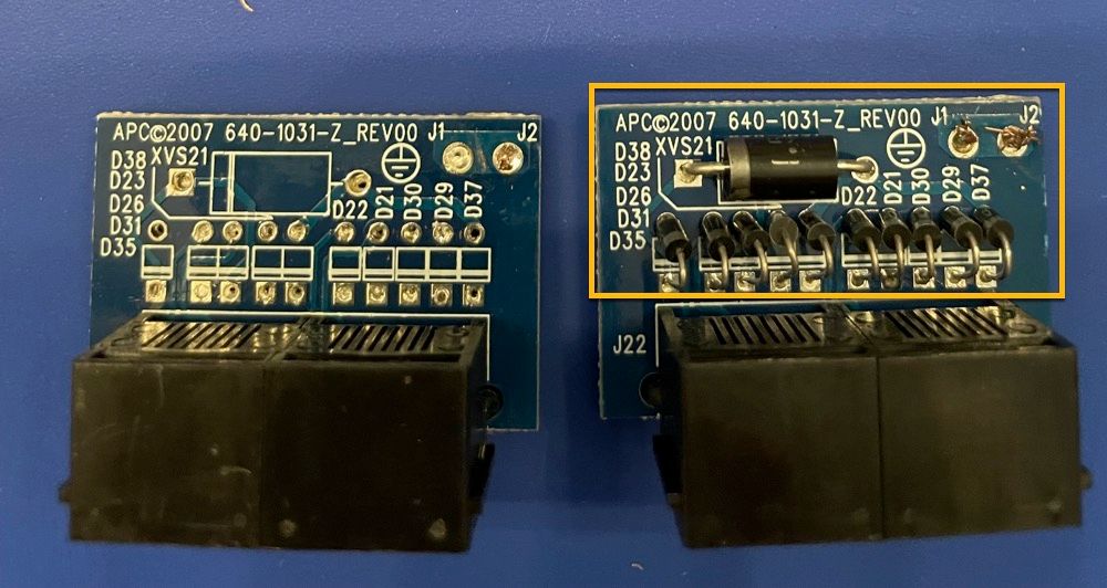
The advantage of this particular APC is the onboard ethernet surge protection. This is also the module that will need to be rewired to support Ethernet for our intended purposes. First order is to locate the module that looks like the following (right-most image) and pull it from the APC housing. There is a small tab that holds it secure, so take your time and gently remove the component.
Once removed, you will want to use either a soldering iron or a hot-air rework gun to desolder and remove all of the diodes as shown in the highlighted box below. The finished product should resemble something similar to the left-most image below.
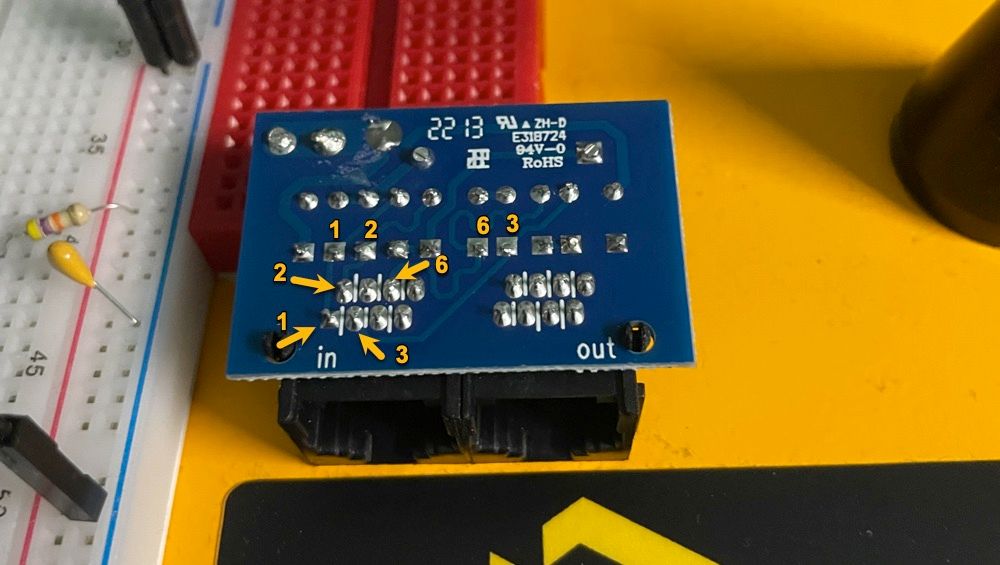
Flipping the Ethernet PCB component over to expose the traces, we can observe the "in" port and the respective pinout. Although it is easy enough to follow the traces on the PCB, the pins and there respective destination solder points are clearly labeled below to remove any confusion.
This is the point where soldering skills will come into play. We recommend using a 22 AWG solid core tinned copper hook-up wire (2-3 inches long) along with a bit of flux at the solder point to make wiring the ethernet connection to the PCB a bit less painful. Then grab an ethernet cable and cut it down to a 6 inch section with the RJ45 plug still intact, and strip the sheathing back about 1 inch.
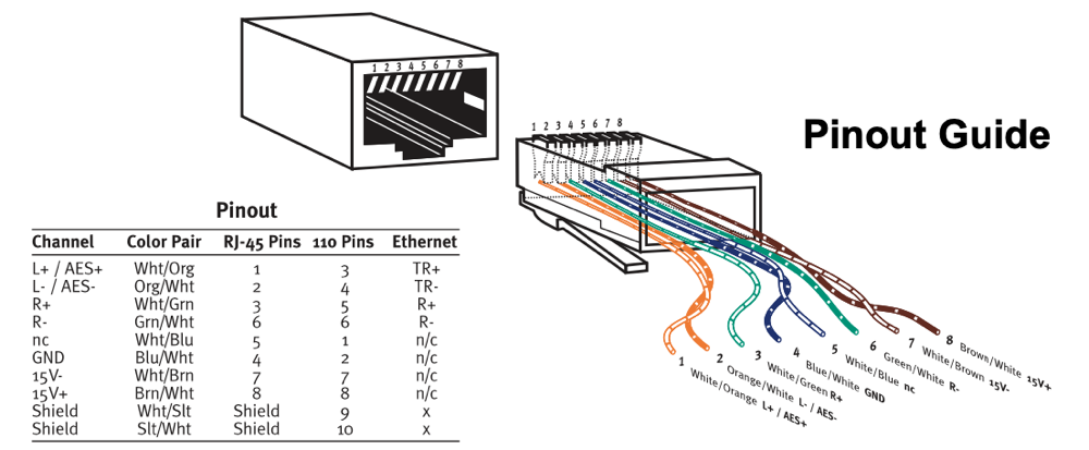
The next task is to wire the ethernet connection to the solid core hook-up wires. The following diagram is for a 568B Ethernet wiring spec, but this is simply soldering pins 1,2,3 and 6 to their respective PCB solid-core hook-up wires.
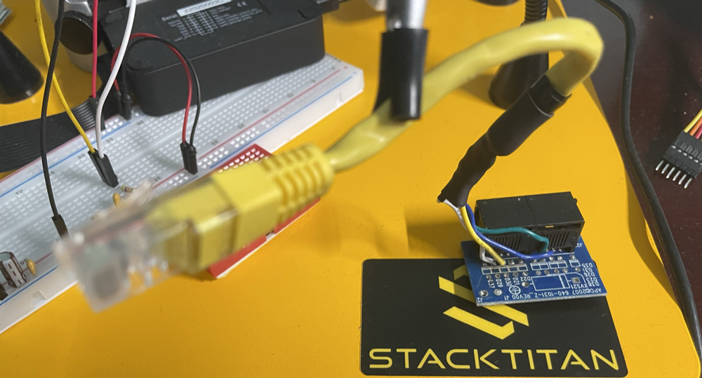
The final product should look similar to the following picture. Also not the gratuitous use of heat-wrap, both for the individual wire connections and the ethernet cable overall. Don't use electrical tape, it is a mess and doesn't instill confidence that your connections are protected adequately.
Wiring the Power Cord
The power cord has a special fitting that holds it securely in the APC case. Unfortunately, it has to be reused and it is a P.I.T.A to repurpose. Specifically, cut the power cord right below the 90 degree fitting. Then strip about 6 inches of sheathing from the cable.
Now you will need to muscle the cut wires out of the 90 degree fitting. It will give way but it does require force to remove the wires. I had to Dremel the inside of the 90 degree fitting so that I could rework the 6 inches or so of wire back through the fitting. This will also take some finesse because it is a tight fit. Once complete, you should have a final product that is indistinguishable from the OEM power cord.
The reason why we had to go through the trouble of reworking the power cord, is because cutting the wiring from the various PCBs during disassembly didn't leave much room to terminate the power, neutral and ground wires to our Leviton plug end. As you can observe in the following picture, we now have even lengths and secure connections.
The following is an illustration of the placement along with the Leviton plug end fitted back into the APC case.
Assembling the Raspberry Pi
This will be a quick step-by-step of the assembly to demonstrate how all of the components fit together. Most readers that are familiar with the Raspberry Pi format should already find it intuitive.
The following is a list of components clockwise from upper-left to include the 128GB MicroSD card, the USB connection cable, the Raspberry Pi 4, the Telik mini-PCI LTE modem connected to the Pulse LTE antenna, and the Sixfab LTE base hat.
Initially, we want to start with the Raspberry Pi 4 and install the Sixfab LTE base hat using brass spacers and screws from the Brass Spacer Standoff Kit. Once secured, it should look like the following.
Note that the use of a header extension will be required, although it should have been included with the Sixfab LTE base hat kit. The following image illustrates the fitment when installed correctly.
Now we are ready to install the actual Telik LTE modem. Connect the u.FL connectors from the Pulse LTE antenna to the Telik board. Ensure the GPS/GNSS and LTE connectors are attached in the correct order. Then simply snap the Telik board into the mini-PCI slot of the Sixfab LTE base hat.
If using the Twilio wireless service, then you will have received a SIM card. This is what we use at STACKTITAN, and it has worked flawlessly with stable daily access running over months-long operations. Install the SIM as follows.
The final task, is to connect the USB cable from the Raspberry Pi's USB-3 port to the micro-USB connection on the Sixfab LTE base hat. The following depicts a completed build ready for placement into the APC.
Final Hardware Assembly of the APC
All of our hard work has paid off and now comes the time to piece it all together. One suggestion is to cut a couple of adhesive backed rubber strips and place them as depicted by the yellow arrows in the following image. This will help to secure the Raspberry Pi and keep it from sliding within the APC. Also, placing a couple of 3M adhesive pads as depicted by the blue arrows will provide a solid surface to adhere the LTE antenna.
Assemble everything into the upper pan of the APC as shown below. Number 1 depicts the Anker block charger and the USB-C cable (straight-end) connections. Number 2 is the location for the ethernet cable connection. Finally, number 3 is the location for the opposing end of USB-C cable (90 degree) mated to the USB-C port on the Raspberry Pi. Make sure to adhere the Pulse LTE antenna, as well.
Now fit the bottom pan to the upper pan and flip the entire APC over. Don't worry about securing the pans together with screws. This is just a test fitment to ensure clearances are adequate. If everything fits, you just successfully assembled your APC covert hardware implant. Flip it back over and remove the bottom pan, so that we can access the Raspberry Pi.
Next Steps...Part 2: CHI OS and Scripting
All of this may have seemed like quite a bit of work to get to this point. Agreed, it does take some time. We have built multiple CHIs; although, the effort is worth it as the CHI performs well in the field. This leads us to the next reason for building such devices.
Remember that Red Team customers are unique in the fact that they often have extended the necessary effort to build out their security programs (people, technology, and processes). A "traditional penetration test" simply is not adequate for such clients, as they want a solution that evolves and grows along with their detection and prevention capabilities. As such, they demand creativity, realistic threat emulations and skilled tradecraft necessary to assess risk from multiple perspectives. If you are an organization that is interested in this style of testing, reach out to STACKTITAN as we would welcome the opportunity to create a custom engagement and talk tradecraft.
We hope this has provided some inspiration for building hardware implants. In the next series of this post, we are going to install the operating system, create scripts to make everything work and finally verify that our CHI is operational.