Preface
This was an interesting journey into what I thought was going to entail lifting data from a typical SPI or I2C chip, but alas it was neither, rather the Microwire protocol. Let's explore this protocol, how we might interface with a Microwire EEPROM and extract data using the newly released Arduino UNO R4 eval board. I mean...this was really just some weekend hacking and a chance to crack open this shiny new Arduino...right?!
Test Environment
The board that we are targeting is a proprietary commercial USB programmer that is used to interface with Texas Instrument MSP430 microcontrollers, and specifically as a means to access SPY-BI-WIRE (SBW). Although, SBW is not the intent of this post but is something that will be a future post as it is an interesting method to multiplex JTAG over a two-wire protocol.
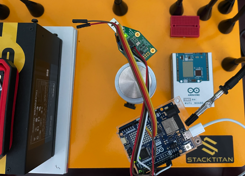
The other important part is selecting the correct GPIO interface for extracting data from the USB programmer's IC. I am just going to say that I started to reach for the Bus Pirate, then I thought about the GreatFet, but realized that I had an Arduino UNO R4 that is a perfectly capable ESP32 enabled eval board. This decision to use the latter actually turned into an ideal exercise to explore the Arduino IDE, write some C, and simply do some experimentation. This is what we are dealing with (Arduino lower side of picture and USB programmer near the top)...
Inspecting the USB Programmer
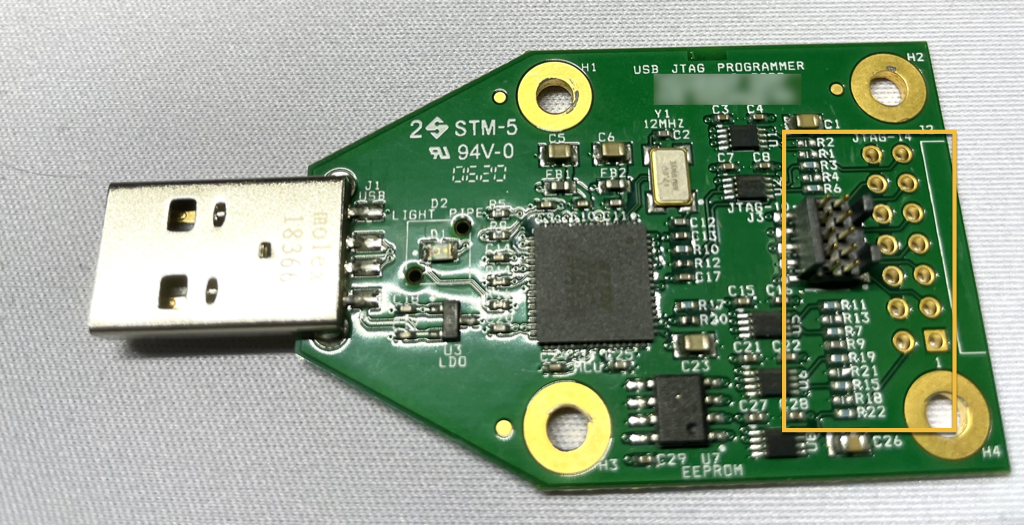
Looking at this device, we can see some interesting items. First, even though this was originally enclosed in a plastic case, is that the manufacturer/designer has not done anything to obfuscate the various interfaces. This is to be expected as it is a programmer and used to interface with target device GPIO, itself. The other obvious items are the M-Cortex and JTAG interfaces on the far right.
Why not just hook up a JTAGulator and bit bang the pins? Well, if we trace the VIAs (i.e., the copper substrate lines) through the PCB, we run into a bank of resistors. The resistors are shielding the components (i.e., MCU and EEPROM) from voltages on the target device. As such, the M-Cortex ( i.e., 10 pin JTAG) and the 14 pin JTAG are simply there as two options to interface with equivalent GPIO on the target device. It is unlikely that the JTAG interface will provide uninhibited access to the on-board component-chain as we might expect.
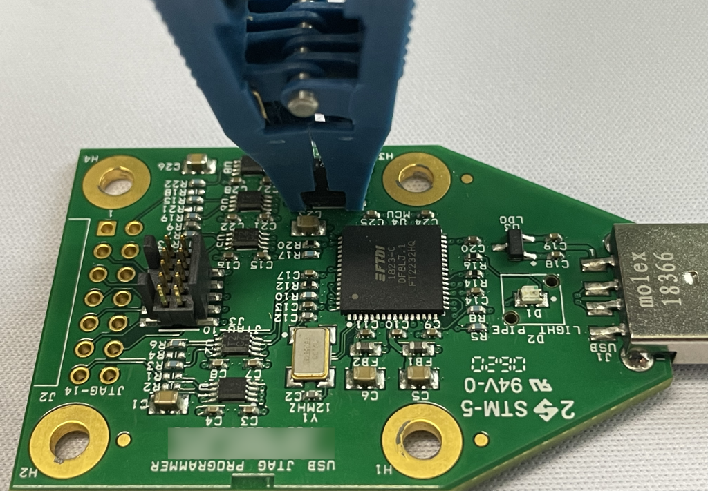
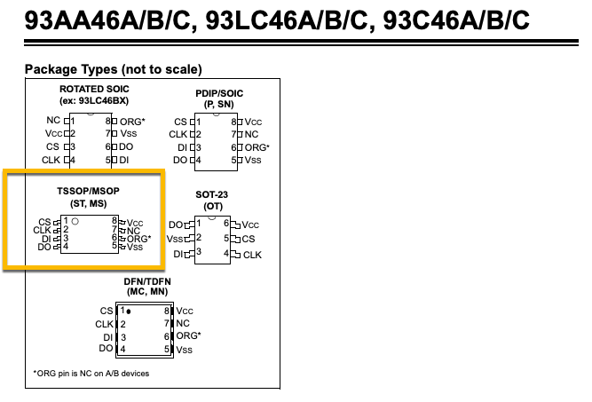
Alternatively, the EEPROM uses a Micro Small Outline Package with exposed legs and the pitch is perfect for a Pomona SOIC 5250 test clip.
Inspecting the EEPROM's Data Sheet
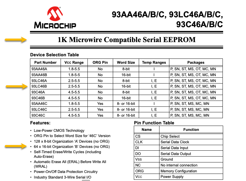
The labeling on this EEPROM was a bit hard to read, so until our stereo microscope arrives, let's just say that it is a Microchip 93LC46B package. The respective data-sheet appears as follows:
Now most everyone has likely been introduced to the SPI or I2C protocols used in serial communications, but this is neither. Instead, this EEPROM uses Microwire. So what is Microwire?
Microwire
Microwire can be thought of as the predecessor to SPI. Whereas SPI utilizes a 4-wire circuit (i.e., MISO - master in slave out, MOSI - master out slave in, CLK/SCK - serial clock, CS/SS - chip select), Microwire uses a 3-wire circuit (i.e., MISO, MOSI, and CLK/SCK). Microwire permits variable length, but is dependent on the type of package and uses the ORG pin configuration to determine memory management (e.g., word size). The other notable item is that Microwire is slightly slower than SPI. Lastly, is that Microwire does not "float" the CS voltage (i.e., neither high nor low), meaning that the voltage is explicitly tied high or low to determine whether or not the chip is actively listening or not.
More about the 93LC46B EEPROM
This particular EEPROM does not support the ORG pin, meaning that the memory Word Size is a fixed 16bit width. Additionally, we might want to know the address bus width, in other words, the number of addresses we have available.
The data sheet states: 64 x 16-bit Organization 'B' Devices (no ORG)
If we have a fixed word size of 16bits and the memory layout is 64 rows, then we can do some quick math to get the address bus width of 6 bits. This will be useful later on.
log2(64) = 6 // 2x2x2x2x2x2 = 64
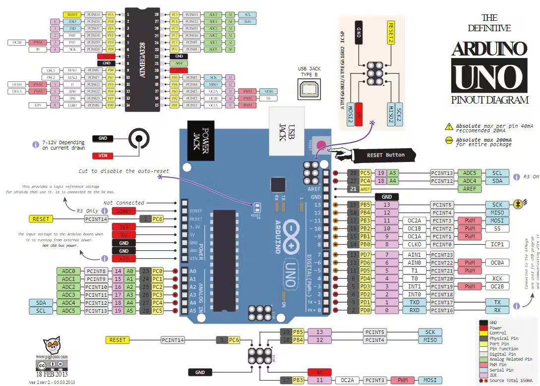
Wiring the Arduino UNO R4 and EEPROM
The Arduino UNO series of boards have numerous prototyping capabilities and the latest ESP32 enabled R4 is much the same layout, but more powerful. The wiring should align with the following table, whereas an Arduino UNO and EEPROM schematic are provided for reference. The finished wiring will look similar to the first picture of this post.
| Data-Sheet Pin | Arduino UNO Pin | Purpose |
|---|---|---|
| CS | 13 | Chip Select |
| DO/MISO | 2 | Master In Slave Out |
| VSS | GND | Ground |
| VCC | 3.3v | Supply Voltage |
| CLK | 12 | Serial Clock |
| DI/MOSI | 7 | Master Out Slave In |
The Arduino IDE and the MicrowireEEPROM lib
I started down the path of reading the data sheet and coding Microwire functionality, but then came upon a couple of usable Microwire Arduino libraries. I don't want to take away from the importance of creating or building from the ground up, but already having an understanding of how the underlying protocol works makes using someone else's research a convenience.
I read through the code for the MicrowireEEPROM and decided that it would be enough to build a usable Arduino Sketch. However, I want to dig into a couple of MicrowireEEPROM.cpp functions as they will help to understand the code we will write, shortly.
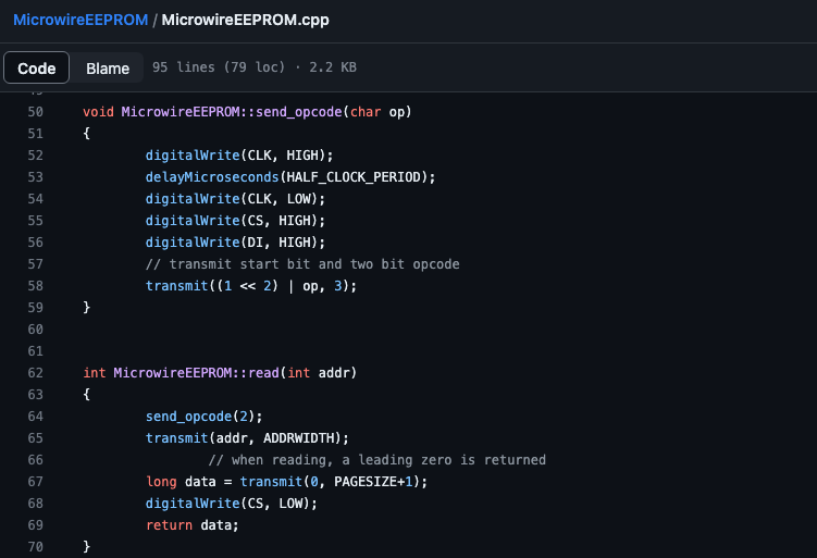
As we want to read the memory of the EEPROM, there are two primary functions, the MicrowireEEPROM::read() and the MicrowireEEPROM::send_opcode(). Note that the read() function requires information about the address width and the page size that we determined early on. As a result, we are going to cycle through all of the 64 memory addresses and read 16 bits of data from each.
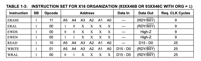
Now, notice that the read() function calls "send_opcode(2)" and passes "2" as it's parameter. Reference the Instruction Set for the 93XX46B package. Notice that the READ instruction has a binary opcode of "10" which is a decimal "2". Also, note how Microwire explicitly controls the state of chip select (CS) when writing and reading, which I had alluded to earlier.
Again, nothing really novel here, but my hope is that this instills an appreciation for the data sheets and how much information is afforded within their pages. They are a wealth of knowledge and extremely useful when reconciling your understanding alongside code.
Writing the Sketch
Finally, we want to leverage the Arduino-IDE to create our code that will be used to read out the data of the EEPROM. The MicrowireEEPROM library has an example sketch called EEPROMTest.ino, which we will use as our foundation. I am going to fast-forward to our code and walk through the functionality.
First, we setup the Arduino UNO pins and map them to their respective functions on line 6. On line 12, we set the address page size and the address bus width, again those are both values we determined earlier on. The other value is serial clock speed which is set to a default 200 microseconds.
#include <MicrowireEEPROM.h>

// Microwire needs four wires (apart from VCC/GND) DO,DI,CS,CLK
// configure them here, note that DO and DI are the pins of the
// EEPROM, so DI is an output of the uC, while DO is an input
int CSEL=13; int CLK=12; int DI=7; int DO=2;

// EEPROMS have different sizes. Also the number of bits per page varies.
// We need to configure the page size in bits (PGS) and address bus width
// in bits (ADW). The speed at which the clock is run is configured in
// microseconds.
int PGS=16; int ADW=6; int SPD=200;

// initialize the library
MicrowireEEPROM ME(CSEL, CLK, DI, DO, PGS, ADW, SPD);

void setup() {
  Serial.begin(9600);
}

void loop() {
  for (int addr=0; addr < (1<<ADW); addr++) {

    // read the value
    uint16_t readValue = ME.read(addr);

    // give some debug output
    Serial.print("Address ");
    Serial.println(addr, HEX);

    Serial.print("Read ");
    unsigned char high_byte = readValue >> 8;
    unsigned char low_byte = readValue & 0xFF;
    char h[7];
    char l[7];

    sprintf(h, "%02x", high_byte);
    Serial.print(h);

    sprintf(l, "%02x", low_byte);
    Serial.print(l);
    Serial.println();

    delay(1000);
  }
}
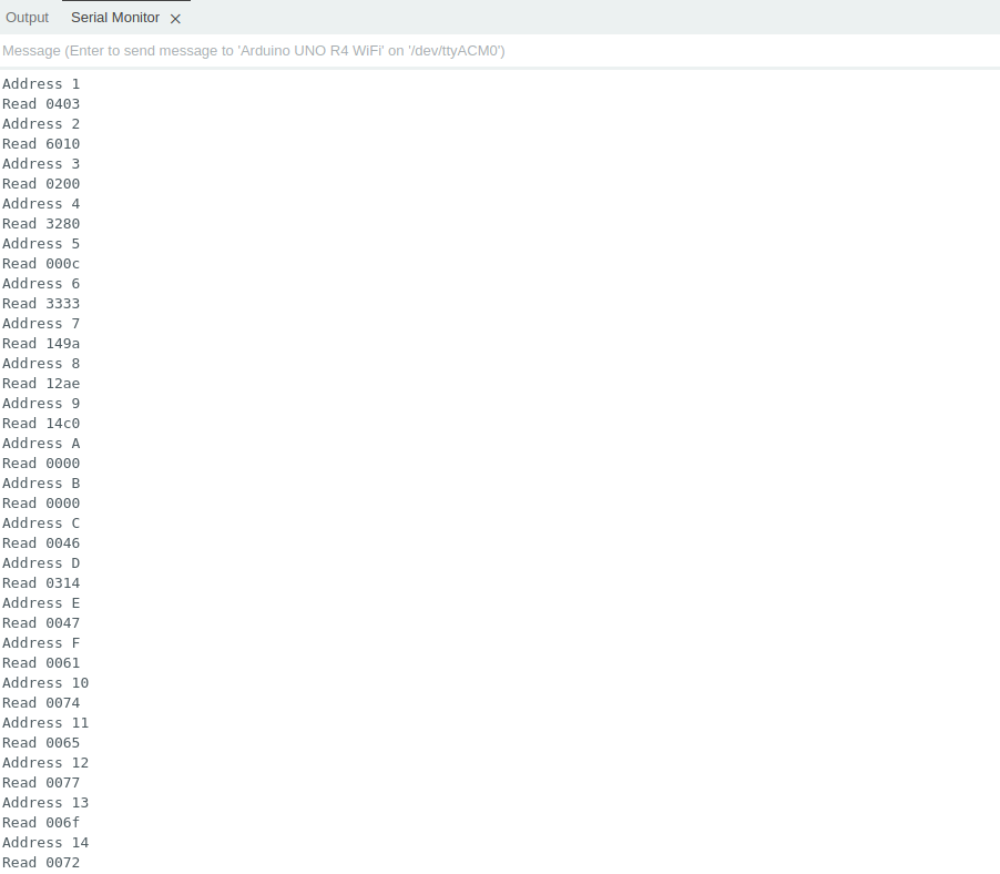
The setup() function is simply to set the serial baud rate to a reasonable value of 9600. The loop() function is performing a bit-shift operation at line 22, which is walking through all of the possible addresses (i.e., 64 total). Line 25, we are using a unsigned 16 bit integer data type to store the data located at a specific memory address.
Lines 32 - 42 require some slight voodoo, which is essentially breaking apart our 16 bit stored value into a lower and upper 8 bit values, respectively. We are doing this so we can "0-pad" string format each byte and then present the lower and upper values as two cleanly formatted bytes. The following screenshot of Arduino-IDE's Serial Monitor illustrates the output produced by our code.
Conclusion
Obviously, there is more that can be done with the data output at this point, which will likely come about as part of a future post. For now, we set out to extract data from this Microwire EEPROM, which we accomplished. It may not be the most elegant solution, but this is hacking and sometimes we just need "it" to work. Having an arsenal of tools at our disposal, including the Arduino UNO R4, is essential to accomplishing our objective. Sure, we could have accomplished the same task with another eval board, but exploring often leads to new discoveries and keeps things interesting. With that, we hope you found this interesting and keep on the lookout for future hardware hacking posts. More on the way!